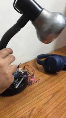
Clappy the Lamp: The Clap controlled reading Lamp
Clappy the Lamp: The clap controlled reading Lamp
Materials needed:
Electronics:
- Arduino Uno
- 2-channel relay (any would work by the way)
- Sound sensor
- Lamp (any, but one with a switch will be easier to use)
- USB Type-A to Type B cable (Arduino cable)
- 5V 1A adapter (a normal phone charger would work too)
- Jumper wires
Tools:
- Hot glue gun (to stick the components)
- Screwdriver and pliers (to open the lamp and get access to the wiring and all...)
(For the code download the files from the link at the bottom)
(I prefer reading the code first)
Working:
The main thing is the code, it uses Booleans. When we clap, the sound sensor sends a HIGH signal and it makes our relay status True or False.
Steps:
1. Open the lamp and take out the on/off switch

(The lamp I used)
2. Remove the switch and connect the relay instead of the switch as shown in the circuit diagram


3. Close the lamp
4. Connect as per the diagram

5. Upload the code
6. Test!!!! and Enjoy!!
7. Make a closure for the electronics for beautification and safety. (Not important)
Code:
The code is considerably simple and easy to understand.
// Declaring the variables for Relay status, relay pin and sound sensor


int soundSensor = 2;
int Relay = 4;
boolean RelayStatus = false;

void setup() {
  pinMode(soundSensor, INPUT);
  pinMode(Relay, OUTPUT);

}

void loop() {
//reading sensor data
  int SensorData = digitalRead(soundSensor);
  if (SensorData == 1) {


//If the relay status is OFF

    if (RelayStatus == false) {
      RelayStatus = true;
      digitalWrite(Relay, LOW);
    }


//If the relay status is ON


    else {
      RelayStatus = false;
      digitalWrite(Relay, HIGH);
    }
    delay(250);
  }
}
Circuit Diagram:

(Relay Connection with live wires as shown)
Relay:
VCC - Arduino 5V pin
GND - Arduino GND (any)
IN 1 - Arduino 4th pin
Sound Sensor:
+ - Arduino 5V pin
G - Arduino GND (any)
DO - Arduino 2nd Pin
(Connect the Arduino to a 5V 1A/2A adapter via a USB Type-A to Type-B cord)
Links for the materials:
(You can use any lamp which has a switch)

waah bro
ReplyDeletemaha shallah kya banaye ho yaar
ReplyDeleteagar tu mujhe pehchan paya ho toh whatsapp kario, iska ss bhejkar
nahi pehchana
Deletetu yaar mere liye iron man suit bhi banade
ReplyDeletebaaki paiso ki chinta mat kar, voh tujhe ambani de dega😁😀
Wow good job animesh
ReplyDeleteGreat work Animesh... Well done👍 keep it up👍
ReplyDeleteGood job, I am proud of you 👏👏
ReplyDeleteVery nice! Look forward to automation of the house now... 😊😊😊
ReplyDeleteAmazing bhai ❤👍
ReplyDeleteThank you all for your appreciation, it means a lot to me
ReplyDeleteVry good animesh keep it up👍🏻
ReplyDelete